Ascend: Streaming Telemetry from 100,000 ft


Today I'll be discussing and analyzing my experience with NASA Ascend, an initiative sponsored by Arizona Near Space Research (ANSR) and the Arizona Space Grant Consortium to design, test, and fly a high-altitude weather balloon payload. Teams from various schools around the state come together twice per year to fly their payloads. The overarching challenge: design a payload that can survive the harsh near-space environment (~100,000 ft) while operating within the constraints set by ANSR.
Our team consisted of nine students and two mentors. Because each ANSR payload is limited to 3 lb. total weight — one of many constraints — we split the team across two separate payloads, which we called the "master" and the "slave" (denoting a hierarchical relationship for controlling data flow). Roughly half the students worked on each board. My personal responsibilities were developing the inter-payload datalink between the two boards, and building a telemetry dashboard capable of decoding data packets received from the payloads while in flight.
The team's main objectives this year were:
- Design and test an inter-payload datalink
- Reliably transmit data over the Iridium modem
- Develop a telemetry dashboard for real-time data decoding
- Conduct a biology experiment in flight
- Fly and test new sensors, including the I²C radio receiver (TEA5767) and the I²C temperature/humidity sensor (AHT20)
Within that scope, my focus was the datalink and the dashboard — the two pieces I'll spend most of this post on.
Software Architecture
An adventure into the software running on both payloads
System Overview
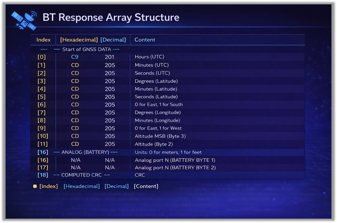
The system described here is the flight and ground software for a high-altitude balloon payload that captures atmospheric, position, and sensor data during flight and streams it to a ground station in near real time. The flight hardware consists of two boards — a master and a slave — that communicate exclusively over a BLE (Bluetooth Low Energy) datalink. The slave hosts the GNSS (Global Navigation Satellite System) receiver and is responsible for packaging position (latitude, longitude, altitude, UTC time) and battery telemetry into a 19-byte response whenever polled by the master. The master runs the task scheduler: it polls onboard I²C sensors (AHT20 humidity/temperature, TEA5767 radio) every two seconds, requests the slave's data over BLE, and every five minutes assembles the accumulated telemetry into a 45-byte packet that the onboard Iridium modem transmits to the ground.
On the ground, transmissions arrive as emails forwarded by the Iridium modem. A C++ program — referred to throughout as the Decoder — authenticates with Gmail, polls for new messages, decodes the hex payload into structured telemetry, and writes JSON files that drive a live web dashboard.
Task Scheduler Design
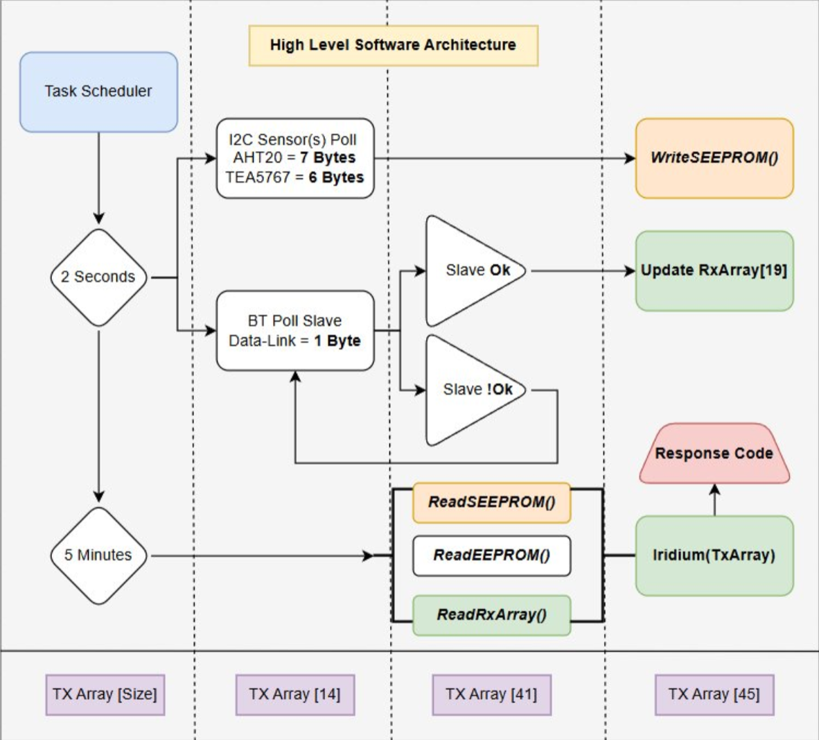
The task scheduler runs two tasks: a 2-second task and a 5-minute task. These intervals are not arbitrary — each is mandated by an Enumerated Requirements list given to us by our mentors and professors Dr. Tim Frank and Rick Sparber.
The 5-Minute Task — Iridium Transmit
The 5-minute interval is driven directly by MODEM 1.0:
"An attempt to transmit data to the Iridium satellites shall be made every 5 ± 0.5 minutes until we have been on the ground for at least 15 minutes."
The scheduler targets a 5-minute transmit attempt interval, well inside the 4.5–5.5 minute tolerance window. The 5 minute transmit rate also allows us to retrieve frequent packets while not going overboard on costs since we are billed per successful tranmission.
The 2-Second Task — Sensor Poll & BT Poll
The 2-second interval is derived from SEEPROM 4.0:
"The data collection rate shall be set such that it will take at least 4 hours to fill this memory and be an integer number of seconds between samples."
This requirement imposes two conditions on the sample interval \(\Delta t\): it must be a positive integer number of seconds, and the resulting fill time must be at least 4 hours. The relevant SEEPROM numbers:
- SEEPROM capacity: 131,072 B (128 KB)
- Header reserved (addr 0–15): 16 B
- Usable for data: 131,056 B
- Record size: 16 B → \(N_{\max} = 8{,}191\) records
The time to fill the SEEPROM at a sample interval \(\Delta t\) is:
$$T_{\text{fill}} = N_{\max} \cdot \Delta t = 8{,}191 \cdot \Delta t$$
Solving SEEPROM 4.0's \(T_{\text{fill}} \geq 4\ \text{h} = 14{,}400\ \text{s}\) constraint for the minimum allowable interval:
$$\Delta t \geq \frac{14{,}400\ \text{s}}{8{,}191} \approx 1.758\ \text{s}$$
Since \(\Delta t\) must be an integer number of seconds, the smallest value that satisfies the requirement is \(\Delta t = 2\) s. A 1-second cadence would fill the SEEPROM in only:
$$T_{\text{fill}}^{(1\text{s})} = 8{,}191 \cdot 1\ \text{s} \approx 2.28\ \text{h}$$
which fails the requirement. Verifying that 2 seconds passes:
$$T_{\text{fill}}^{(2\text{s})} = 8{,}191 \cdot 2\ \text{s} = 16{,}382\ \text{s} \approx 4.55\ \text{h} \;\geq\; 4\ \text{h} \;$$
A 2-second cadence is therefore the optimal choice: it is the smallest integer interval that satisfies SEEPROM 4.0, which means it gives the highest resolution allowed under the requirement while still guaranteeing more than 4 hours of recording capacity. For a planned 2-hour flight, this consumes:
$$B_{\text{used}} = \frac{T_{\text{flight}}}{\Delta t} \cdot 16\ \text{B} = \frac{7{,}200\ \text{s}}{2\ \text{s}} \cdot 16\ \text{B} = 57{,}600\ \text{B}$$
or roughly 44% of the SEEPROM, leaving a 2.27× safety margin against the maximum recording time.
The BT poll of the slave rides on the same 2-second interval. The BLE exchange completes in well under this timeframe, so the poll inherits the cadence at no additional cost — keeping the GNSS and battery snapshot fresh between Iridium transmits costs nothing and simplifies TX-array assembly at the 5-minute mark.
Implementation Of The Task Scheduler
void loop()
{
    ...
if(BT_EQUIPPED_BOOL) {
	btUpdate(); // 2-second task: Poll Slave For Latest GNSS and BATT
};
I2CstateMachines();     // runs AHT20 + Radio scanner state machines every loop
task2SecSEEPROMwrite(); // 2-second task: Write I2C Block to SEEPROM
iridiumScheduler();     // 5-minute task: build TX array and transmit
    ...
}
Task Scheduler Functions Within the loop running on core 0
The main loop contains four high-level functions responsible for every critical feature on the master board: btUpdate(), I2CstateMachines(), task2SecSEEPROMwrite(), and iridiumScheduler(). These can be grouped into two categories — 2-second tasks and 5-minute tasks. We begin with the 2-second tasks, since they produce the data that the 5-minute task depends on.
The 2-Second Tasks: Data Acquisition
void task2SecSEEPROMwrite() {
    if ((millis() - task2SecTimerULong) < TASK_2SEC_INTERVAL_UL) {
        return;
    }
    task2SecTimerULong = millis();  // reset 2-second timer
    // --- SEEPROM overflow guard ---
    if (seepromFullBool) {
        return;
    }
    if ((seepromWriteAddressLong + 16) > SEEPROM_MAX_ADDRESS_LONG) {
        seepromFullBool = true;
        return;
    }
    assembleI2Cblock();
    if (memcmp(latestI2Cblock, previousI2Cblock, 16) == 0) {
        return;
    }
    for (byte i = 0; i < 16; i++) {
        fdr.WriteSEEPROM(seepromWriteAddressLong + i, latestI2Cblock[i]);
    }
    memcpy(previousI2Cblock, latestI2Cblock, 16);
    seepromWriteAddressLong += 16;
    seepromUpdateHeader();
}
task2SecSEEPROMwrite() structure
The 2-second task is implemented in task2SecSEEPROMwrite(). Each tick the function assembles the latest I²C sensor snapshot into a 16-byte block and writes it to SEEPROM using fdr.WriteSEEPROM(), a library function written by R. G. Sparber. Before every write, the function checks seepromFullBool — a runtime flag that, once tripped, halts all further writes so the most recent data is preserved. The flag is set when the next 16-byte record would exceed SEEPROM_MAX_ADDRESS_LONG, ensuring we never overwrite earlier flight data once the chip is full. After a successful write, seepromUpdateHeader() writes the new seepromWriteAddressLong and record count back into the 16-byte persistent header at addresses 0–15. This header is what allows the SEEPROM to survive a reboot — on next power-up the header is read first and writing resumes exactly where it left off. As a final optimization, the function compares the newly assembled block against the previous one (previousI2Cblock) and skips the write entirely if nothing has changed, avoiding unnecessary write cycles.
assembleI2Cblock()
void assembleI2Cblock() {
    latestI2Cblock[0]  = Radio_sweep_count_byte; // Sweep counter
    // AHT20 sensor data
    latestI2Cblock[1]  = AHT20record[0];               // humidity byte 0 (MSB)
    latestI2Cblock[2]  = AHT20record[1];               // humidity byte 1
    latestI2Cblock[3]  = AHT20record[2];               // humidity byte 2 (LSB)
    latestI2Cblock[4]  = AHT20record[3];               // temp byte 0 (MSB)
    latestI2Cblock[5]  = AHT20record[4];               // temp byte 1
    latestI2Cblock[6]  = AHT20record[5];               // temp byte 2 (LSB)
    latestI2Cblock[7]  = AHT20record[6];               // AHT20 status
    // TEA5767 Radio data
    latestI2Cblock[8]  = (byte)(Last_scanned_station_idx >> 8);
    latestI2Cblock[9]  = (byte)(Last_scanned_station_idx & 0xFF);
    latestI2Cblock[10] = Last_scanned_station_signal_strength;
    latestI2Cblock[11] = (byte)RadioStereoBool;
    latestI2Cblock[12] = datalinkByte; // 0=good BT datalink, 1=bad BT datalink
    latestI2Cblock[13] = Radio_peak_signal_this_sweep;
    // MODEM 2.0 — last modem return code
    latestI2Cblock[14] = (byte)((seepromLastModemCodeUInt >> 8) & 0xFF);
    latestI2Cblock[15] = (byte)( seepromLastModemCodeUInt       & 0xFF);
    }
assembleI2Cblock() structure
The assembleI2Cblock() function gathers 7 bytes from the AHT20 temperature and humidity sensor. These come from AHT20record[], an array containing the latest sensor data, which is kept up to date by a driver written by Caden Hess. Another 6 bytes are sourced from the TEA5767 FM radio driver, written by Justin Thomas. The datalinkByte — updated inside BTupdate(), which we'll cover in detail in the next section — carries the current status of the BLE datalink and is also packed into the block. Finally, the modem return code is written to SEEPROM in compliance with the Second Semester Enumerated Requirement MODEM 2.0: "All failure return codes shall be stored in SEEPROM."
The Datalink and BtUpdate()
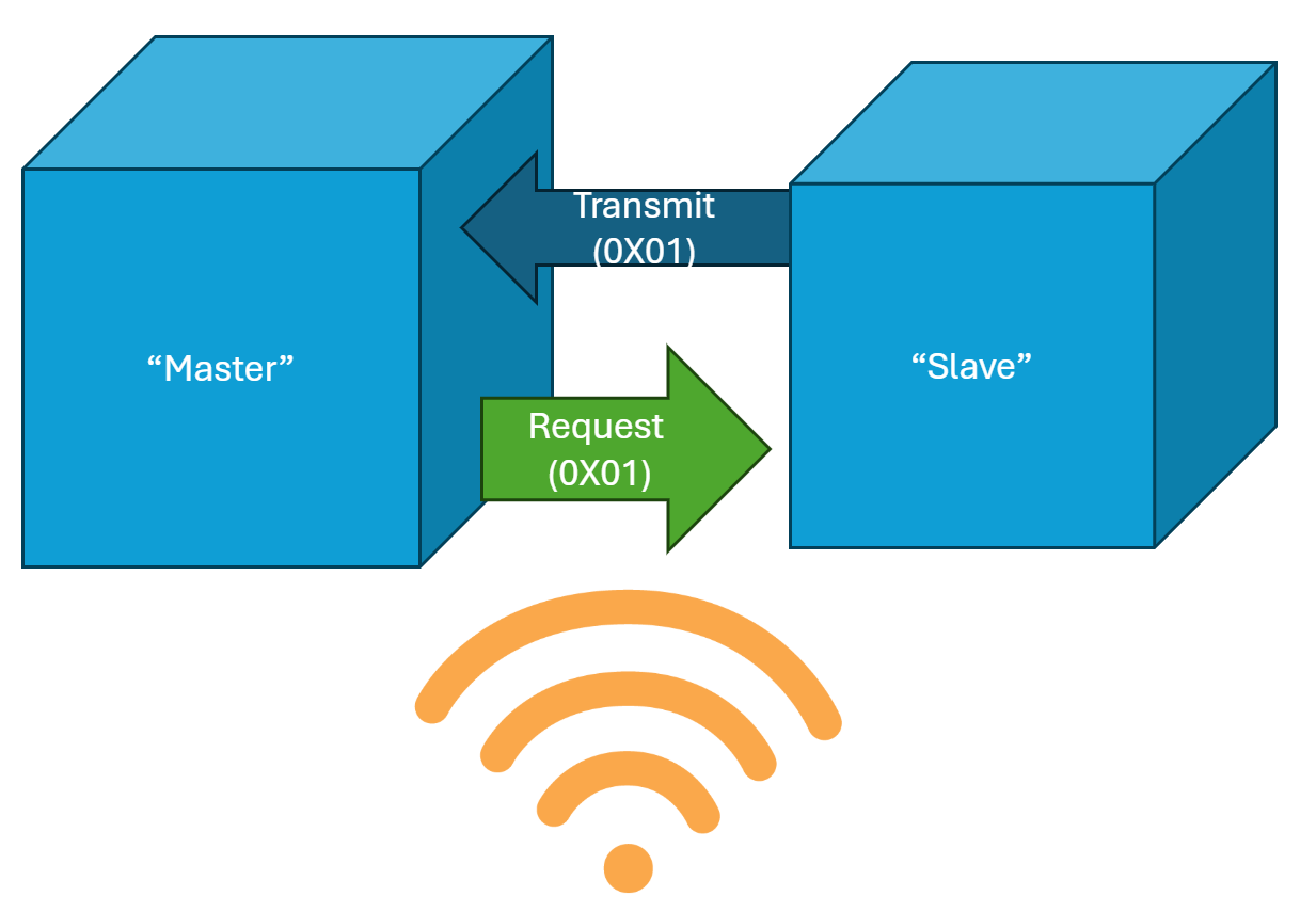
The btUpdate() function is responsible for polling the slave using BT_SLAVE_REQ, an agreed-upon request byte equal to 0x01. The slave monitors its RX buffer for 0x01 and, upon receiving it, immediately sends back a 19-byte packet. The structure of that packet is shown below. A short video demonstrating the protocol in real time is also included.
Live Datalink Test
The btUpdate() State Machine
The function is implemented as a state machine to keep it real-time friendly — no blocking calls, no waits that hold up the rest of the main loop. The retry logic is minimal: the slave is given 500 ms to respond after the initial poll, and if it fails to answer in that window, it is skipped until the next 2-second polling interval. There is no benefit to anything more aggressive since if the payload is in flight and the slave isn't responding, the only option is to keep polling until it comes back. The structure of the btUpdate() state machine is shown below.
void btUpdate() {
    switch (btState) {
        case BT_IDLE:
                ...
                Poll Slave And Wait
                btState = BT_WAIT_RESPONSE
                ...
        case BT_WAIT_RESPONSE:
            if (Bytes Exist) {
                ...
                Read Recieved Bytes
                ...
                btState = BT_READING;
            } else if (TimeOut) {
                ...
                No Response From Slave
                ...
                btState = BT_ERROR;
            }
        case BT_READING:
            while (Bytes Available) {
                Read Bytes Until Empty
            };
            } else if (TimeOut) {
                ...
                Trigger and Error If We Did Not Get Full Packet
                ...
                btState = BT_ERROR;
            }
        case BT_COMPLETE:
            if (Valid Array) {
                ...
                Reset Valid Array Flags and Go Back to Idle
                ...
            }
            btState = BT_IDLE;
            break;
        case BT_ERROR:
            if (We Tried Twice) {
                ...
                Wait Two Seconds
                ...
            } else {
                ...
                Try Again
                ...
            }
    }
}
high level btUpdate() state machine
The 5-Minute Task: TX Array Assembly & Iridium Transmit
Every five minutes the payload sends a 45-byte packet up to the Iridium constellation, which forwards it down to our ground dashboard. The function responsible for this is iridiumScheduler(), and like btUpdate(), it's structured as a state machine. The states are:
ISCHED_IDLE— waiting for the next scheduled transmit windowISCHED_BUILD— refreshing the I²C sensor snapshot and packing the 45-byte TX arrayISCHED_TRANSMIT— handing the array to the Iridium modem and attempting to transmitISCHED_AWAIT— reading the modem's response code and deciding whether the transmit succeededISCHED_COOLDOWN— small interstitial state to cleanly fireIDLEon the next scheduler tick
High level code for the scheduler:
void iridiumScheduler() {
    if (No Modem Fitted) return;

    switch (iridiumSchedState) {
        case ISCHED_IDLE:
            if (Scheduled Delay Elapsed) {
                iridiumSchedState = ISCHED_BUILD;
            }
            break;

        case ISCHED_BUILD:
            ...
            Refresh I2C Sensor Snapshot
            Pack the 45-byte TX Array
            ...
            iridiumSchedState = ISCHED_TRANSMIT;
            break;

        case ISCHED_TRANSMIT:
            ...
            Suppress Loop 1 Cycle Time Monitor
            Fire Iridium Transmit
            ...
            iridiumSchedState = ISCHED_AWAIT;
            break;

        case ISCHED_AWAIT:
            Read Modem Return Code
            if (Code Is Still in "In Progress" Range) break;

            ...
            Stash Current Code Into Previous, Latch New Code
            ...

            if (Transmit Successful) {
                ...
                Schedule Next TX in 5 Minutes
                ...
            } else {
                ...
                Use Code-Specific Retry Delay
                ...
            }
            iridiumSchedState = ISCHED_COOLDOWN;
            break;

        case ISCHED_COOLDOWN:
            if (Cooldown Elapsed) {
                ...
                Force IDLE to Fire Immediately Next Tick
                ...
                iridiumSchedState = ISCHED_IDLE;
            }
            break;
    }
}
Why a state machine here?
The modem can't be talked to synchronously. Also if we blocked the entire loop on Iridium.transmit(), we would surly run into excessive loop time issues (this was an ongoing problem thought testing). Splitting the transmit across multiple loop iterations means everything else keeps running while the modem does its thing.
ISCHED_BUILD — packing the 45 bytes
This is where the payload's data actually gets shaped into the transmit format. The TX array is 45 bytes wide, and every byte has a specific meaning. The dashboard, on the receiving end, needs to know exactly where each value lives.
The layout we settled on:
| Byte(s) | Field | Source |
|---|---|---|
| 0 | Datalink status (0 = good BT link, 1 = bad) | datalinkByte |
| 1–16 | GNSS data from Slave (via BT) | lastValidBtRx[0..15] |
| 17–32 | Latest I²C sensor block (AHT20 + radio) | latestI2Cblock[] |
| 33 | Current modem return code MSB | iridiumCurrentStatusUInt >> 8 |
| 34–35 | Master battery voltage (raw int, MSB then LSB) | analogRead(29) (RP2040 internal ADC) |
| 36–37 | Internal analog temperature | fdr.ADCread(ADC_PORT_INT_TEMP) |
| 38–39 | External analog temperature | fdr.ADCread(ADC_PORT_EXT_TEMP) |
| 40–41 | Slave battery (from last valid BT packet) | lastValidBtRx[16..17] |
| 42 | Current modem return code LSB | iridiumCurrentStatusUInt & 0xFF |
| 43–44 | Previous modem return code (full 16-bit) | iridiumPreviousStatusUInt |
A few things worth pointing out about this layout:
Byte 0 is the datalink byte. Putting the BT datalink status as the very first byte is intentional because the dashboard reads this first and uses it to decide whether to trust the GNSS fields in bytes 1–16. The GNSS unit byte is also used to know if we can plot altitude data. If the master never successfully received a BT packet from the follower, bytes 1–16 are zeros from initialization, and the dashboard needs to know not to plot those as a real coordinate. (This actually was a bug during flight, however it is now fixed)
Multi-byte values are split MSB/LSB. The multibyte sensor and GNSS values are split — high byte first, then low byte. The dashboard reassembles them with (byte_msb << 8) | byte_lsb.
The modem status code gets two slots. Bytes 33/42 hold the current return code, bytes 43/44 hold the previous one. Why both? Because the dashboard needs to be able to tell the difference between "this packet was sent during a healthy link" (current = 0–4) and "this packet was the first successful transmit after a string of failures" (previous code in the failure range, current code = success).
ISCHED_AWAIT — interpreting the modem's return code
This is where the response-code-driven retry logic actually lives. The modem returns a numeric code indicating what happened. A separate helper function, getIridiumRetryDelayMs(code), maps each failure code to a recommended retry delay:
unsigned long getIridiumRetryDelayMs(unsigned int code) {  // Thanks Daniel
    if (code <= 4) return 0;                  // satellite success — use 5-min interval
    switch (code) {
        case 10: return  30000UL;             // call did not complete in allowed time
        case 11: return  60000UL;             // GSS MO queue full
        case 17: return  30000UL;             // gateway not responding (local timeout)
        case 18: return  15000UL;             // connection lost / RF drop — retry quickly
        case 33: return  60000UL;             // antenna fault
        case 35: return  10000UL;             // ISU busy — retry soon
        case 36: return 180000UL;             // must wait 3 min since last registration
        // ... (full table in the source)
        default: return 30000UL;              // unknown — default 15 s
    }
}
Without code-specific delays, the simple alternative would be to just retry every 5 seconds on any failure. I think we can do better then that :)
ISCHED_COOLDOWN — the cleanup state
Mostly housekeeping. Once we know the transmit's outcome, we need to schedule the next one — either in 5 minutes (success) or after the code-specific retry delay (failure). The COOLDOWN state forces IDLE to fire on the very next scheduler tick.
Transition to the dashboard
This all naturally raises a next question: how do those 45 bytes actually get from the Iridium satellite constellation back to a webpage running in a browser? That's where the dashboard comes in.
The Telemetry Dashboard
The 45-byte TX array is only useful if someone on the ground can actually read it. It's important to note that there's no direct connection between the satellite and the browser. The packet has to traverse three independent layers of software before any of its bytes show up as a number on a screen.
The pipeline:
- C++ ingestion service — polls Gmail for new RockBLOCK forwards, decodes the hex payload, writes structured JSON
- JSON files — the only contract between the backend and the frontend
- JavaScript frontend — fetches the JSON, renders the UI, plots the map and charts
Why Gmail?
Before getting into the layers, this question deserves an answer because it sounds weird: why is the dashboard reading email?
The Iridium constellation's standard delivery mechanism for short-burst data is to forward each received packet as an email. RockBLOCK (the modem provider) does exactly this — every transmit from the payload arrives as an email to a registered address with a fixed format:
IMEI: 300534065390120
MOMSN: 150
Transmit Time: 2026-03-28T18:32:57Z UTC
Iridium Latitude: 33.0361
Iridium Longitude: -111.6741
Iridium CEP: 3.0
Iridium Session Status: 0
Data:
524200000001121f0a210327006f2914010000018a00...
After doing some research I do believe RockBLOCK supports HTTP webhooks, but the Google Gmail API is free and more straight forward for our use case. I setup the account via google cloud console and created a service account. I then got the credentials and stored them locally on my laptop. The service then authenticates with Google's API and polls the inbox once a minute, looking for new messages from the modem's address.
Layer 1: C++ Ingestion Service
The backend is a C++ program that does five main things on a loop:
while (true) {
    Authenticate with Gmail (refresh token if expired)
    Search inbox for new emails from modem address
    For each new email:
        Extract the hex payload from the body
        Decode the 50 bytes into a structured PayloadData
        Append to telemetry history
    Write the full history to telemetry.json
    Sleep 1 minute
}
The codebase splits naturally across four classes, each handling one concern:
| Class | Job |
|---|---|
GmailAuth | OAuth 2.0 flow — initial code exchange, token caching, refreshing expired tokens |
GmailClient | Searching the inbox, fetching message bodies, base64-decoding email parts |
Decoder | Parsing the email body for the hex string, then converting the 50 bytes into a PayloadData struct |
Logger | Timestamped logging to both a file and an in-memory ring buffer (for the live log panel) |
OAuth 2.0 was the hardest part. Google's OAuth flow is a multi-step process: the user gets redirected to a Google login page, copies an authorization code from the URL, pastes it back into the program, the program exchanges that code for an access token + refresh token, the access token expires every hour, and the refresh token is used to silently get new access tokens. Then once that's set up, you have to handle the refresh token itself rotating, network errors, and cached state across restarts. And on top of this, it was my first time actually doing all of this from scratch. I've interacted with API's but mostly using libraries that others have written. I wanted to challenge myself with this. It took many late nights...
The GmailAuth class boils this down to a single authenticate() method that handles all of it. The first run prompts the user to do the browser copy and paste once. After that, the refresh token persists in env/token_cache.json and the program is hands-off forever. Every subsequent restart silently renews the access token and proceeds.
The Decoder takes a hex string like 524200000001121f0a210327006f2914... and turns it into a fully populated PayloadData struct. The mapping is byte-precise and matches the layout from buildIridiumTxArray() exactly.
The 50 bytes break down as:
[0..1]    "RB" header (manufacturer)
[2..4]    Modem serial number (3 bytes big-endian)
[5..49]   The 45-byte TX array we built on the payload
Inside the TX array, the decoder reverses every encoding step fdr.ino did when it built the array. Some samples:
// Master battery: raw 12-bit ADC × ADC step × divider compensation
float voltage = rawADC * 0.80566e-3f * 4.3f;

// AHT20 temperature: 20-bit raw → °C using datasheet formula
float tempC = ((B0 * 65536 + B1 * 256 + B2) * 200.0f / 1048576.0f) - 50.0f;

// External analog temp: voltage → °C using calibration constants
float tempC = (voltage - 0.491f) / 0.011f;

// Modem return code: reassemble 16-bit value from MSB and LSB bytes
uint16_t code = (msb << 8) | lsb;
Every constant in those formulas (0.80566e-3, 4.3, 0.491, 0.011, 65536, 1048576) comes from our empirical calibrations for each sensor. Both sides — payload and dashboard — keep these constants in sync.
Output: a single JSON file. After every poll cycle, the entire telemetry history gets serialized into dashboard/data/telemetry.json. The full payload structure looks like this for one record:
{
  "momsn": 150,
  "imei": "300534065390120",
  "transmitTime": "2026-03-28T18:32:57Z",
  "iridiumLatitude": 33.0361,
  "iridiumLongitude": -111.6741,
  "hexData": "524200000001121f0a210327...",
  "payload": {
    "datalinkByte": 1,
    "btLinkGood": false,
    "gnssValid": true,
    "latitude": 33.060833,
    "longitude": -111.688889,
    "altitude": 394,
    "aht20": { "humidityRH": 18.90, "tempC": 31.32, "tempF": 88.38, "status": 2 },
    "radio": { "frequencyMHz": 99.30, "signalStrength": 2, "stereo": false },
    "sensors": {
      "masterBattery": { "voltage": 1.50, "measurement": 6.44, "unit": "V" },
      "slaveBattery":  { "voltage": 0.56, "measurement": 6.94, "unit": "V" },
      "internalTemp":  { "voltage": 0.87, "measurement": 33.50, "unit": "°C" },
      "externalTemp":  { "voltage": 0.76, "measurement": 24.60, "unit": "°C" }
    },
    "modem": {
      "currentCode": 32,  "currentDesc": "No network service",
      "previousCode": 269, "previousDesc": "Signal strength too low"
    }
  }
}
Layer 2: The JSON Layer
This isn't really a "layer" so much as an easy interface for the frontend to work with. Two files get written:
telemetry.json— the full flight history, one entry per received packetlogs.json— recent log lines for the live log panel on the dashboard
Both are written atomically by the C++ backend and re-read periodically by the JavaScript frontend.
Layer 3: JavaScript Frontend
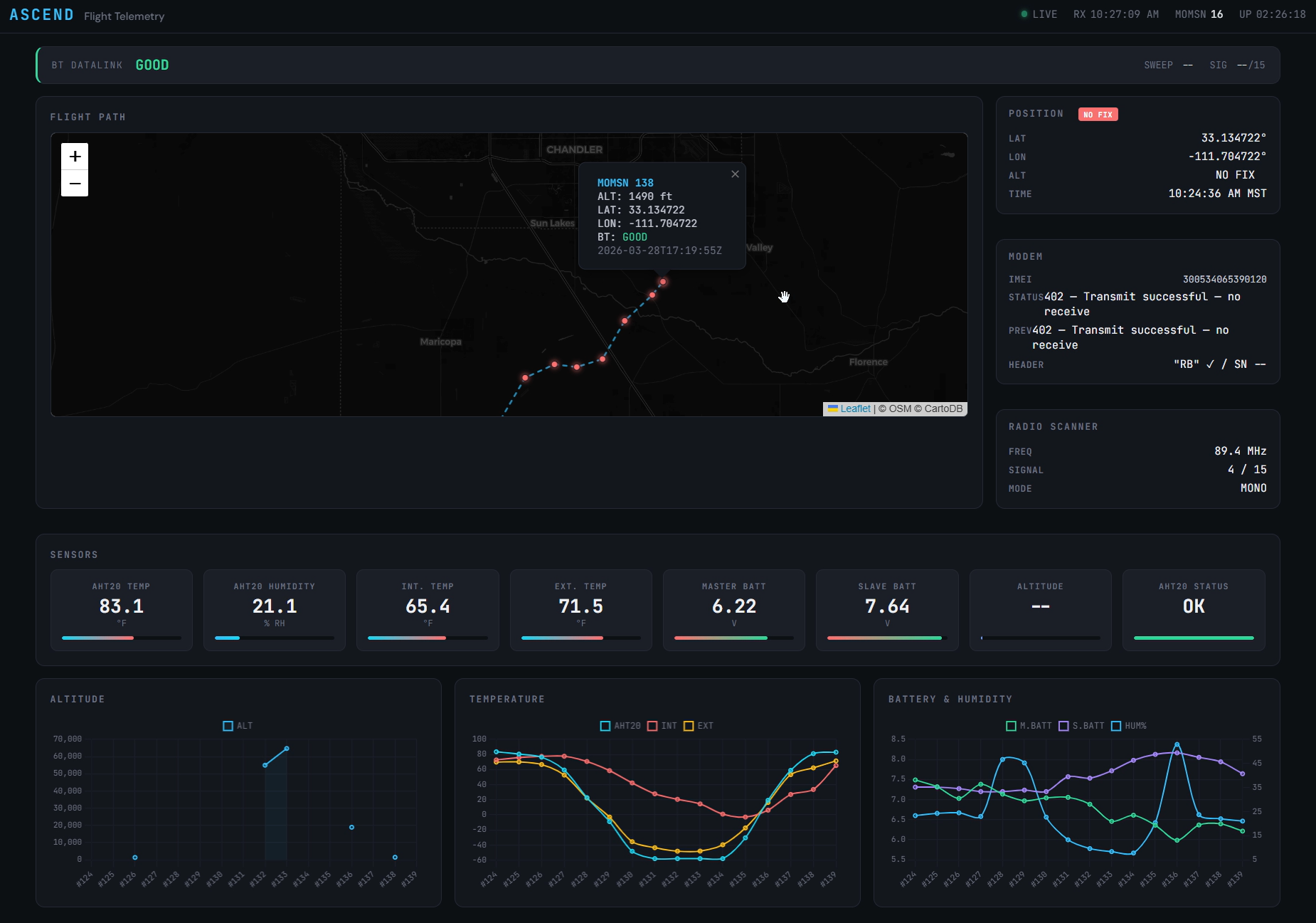
The frontend is plain HTML/CSS/JavaScript. Just index.html, style.css, and dashboard.js, served as static files. The program is very simple: every couple of seconds, fetch telemetry.json, parse it, and update the webpage.
The UI breaks down into these regions:
| Region | What it shows |
|---|---|
| Status bar (top) | LIVE indicator, last RX time, current MOMSN, dashboard uptime |
| BT Datalink strip | Master/follower link health (the datalinkByte from byte 5) |
| Flight Path map | Leaflet map with the GPS track, color-coded by datalink status |
| Position / Modem / Radio cards | Latest GPS coords, modem return code with description, FM scanner state |
| Sensor gauges | AHT20 temp & humidity, internal/external analog temp, both battery voltages, altitude |
| Charts | Three Chart.js plots — altitude, temperature, battery + humidity |
| Hex dump | The full 50-byte raw packet, color-coded by field meaning |
| System Log | Live tail of the C++ logger's output, with severity filtering |
The BT datalink strip is a single horizontal bar that turns green when datalinkByte == 0 and red when it's anything else. The reasoning: if the BT datalink is down we would like to know. It turned out to be very useful during our flight.
Charts use MOMSN as the X-axis, not time. MOMSN (Mobile-Originated Message Sequence Number) increments on every transmit. Using it instead of a timestamp means gaps in the data show up clearly as missing X values. If MOMSN jumps from 134 to 137, the chart shows that gap explicitly.
A cool future feature and Summary
No commanding. The dashboard is read-only. We can't tell the payload to do anything from the ground. Iridium does support it but unfortunately we were under strict time constraints.
Summary
The dashboard ran for the entire flight without intervention, decoded every received packet, and gave us real-time visibility into both the payload's state and the modem's link health. I think it served its job well and I think i will continue to improve upon it and make it better.